![]()
Contents: Personal Selections; The Antennas; Cap Hats; The Amplifiers; The Controller Boxes; Video Display; Odds & Ends;
There are good reasons why I have what I have. For the most part, it is because I have actually used and/or rejected most of the other currently-available gear. This includes antennas, transceivers, amplifiers, and antenna controllers. That in itself doesn't mean the other gear wasn't worth the price of admission, albeit sometimes that was the case. Call it personal preference if you wish. However, some of the available gear I wouldn't own on a bet, whether I have personally tested them or not. A good example are the various short, and stubby antennas which have become the current rage. It is important to remember this simple fact: In any mobile installation, the establishes the least common denominator!
On-line reviews don't mean much either. For example, the Yaesu ATAS series consistently rates 4+ out of 5 stars, yet it is the lossiest, most trouble-prone, remotely tuned, HF mobile antenna money can buy. They're prone to common mode problems (as mentioned in the owner's manual), and if you live in a very cold, or very hot part of the country, you'll find they don't work in either extreme. In spite of all of this, until recently, it was the number one selling, remotely-tuned, HF mobile antenna in the USA.
Here's another truth: The price you pay is not always an indicator of quality, workmanship, longevity, or even as an implied warranty. It doesn't correlate to efficiency, or ease of use either. Whatever selection you make, the best advise I can offer is this—if at all possible, try it, before you buy it!
Over the years, I've used about 20 different commercial HF antennas, and a lot of home brew ones too. One of the remotely tuned ones turned out to be almost a dummy load on the upper bands, although it worked passively on the lower ones.
 I've never liked the mounting arrangement (U bracket) that most larger screwdriver antennas use, for several reasons. First, placing the base of the antenna well above its ground plane increases losses and common mode current. The insulator at the top of the bracket isn't robust in most cases, and eventually arcs over. And if you're an off-roader, guess where the mast breaks off? The mounting style also limits where and how you install the antenna.
My HF antenna is a Scorpion 680, mounted in the bed of my Honda Ridgeline, directly over the cross brace protecting the fuel tank. It is, in fact, the best made screwdriver antenna available, as any owner will attest to. Unlike most screwdriver antennas, the mast is made of 304 stainless steel, 3" OD x .125".
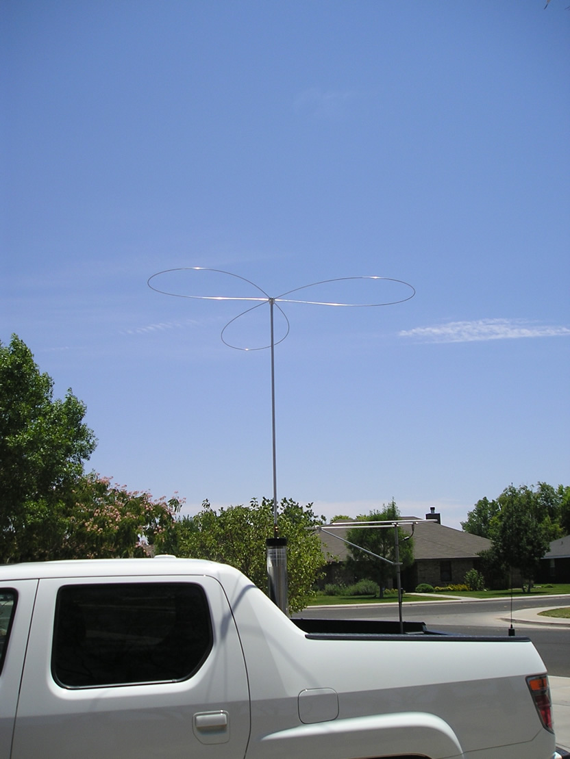
The 6 meter antenna is an M-Squared HO Loop. It isn't mounted as high as I would like (I garage my Ridgeline), but it operates fairly well all considering. Here is a 6 meter fact, which any newcomer to the band needs to know. Most propagation on 6 meters is via the F2 layer, which twists vertically polarized signals to horizontally polarized ones. As a result, a vertical antenna will have a 20 dB disadvantage over a horizontally polarized antenna. In other words, if you're serious about 6 meter mobile operation, a loop is a very wise investment.
The very first VHF antenna I ever bought (1971) was a Larsen NMO150. I still own it, and it is still in near daily use. It has been installed on at least 20 vehicles, and atop about a dozen NMO mounts (I usually leave them in place when I trade). The current VHF antennas are both Larsen NMO2/70BK dual banders. One is mounted on its fifth vehicle. I've crunched it twice with the garage door, and it is still working perfectly. You can't say that about any import. There are more photos of my installation here.
 For about 4 years, I played with a variety of cap hat designs. Ken Muggli, KØHL, helped me by building most of the requisite mounting hubs. If you have read the highlighted article, you'd know why we spent the time exploring the various possibilities. Cap hats increase the radiation resistance (Rr) by raising the antenna's current node. It is not uncommon to achieve a ≈3 dB increase over the field strength compared to the same antenna using just a 102 inch whip, and as much as 6 dB on the lower bands (160, 80, and 40)!
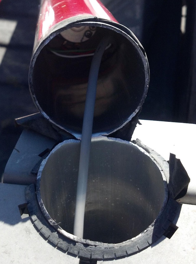
The cap hat is mounted atop a 5/8 inch, by 48 inch, 6160T6 aluminum mast. The three loops are made from 304 stainless steel, .125 by 72 inch long rod. The complete assembly weighs in at just 9 ounces. The effective outer diameter is ≈58 inches. Mounted atop the mast—the correct position for any cap hat—its equivalent electrical length is ≈120 inches depending on the frequency of operation. The tip of the cap hat remains below 13 feet, even on 80 meters.
When I first installed the cap hat as shown, a problem arose when attempting to use 6061T6 for the loop wires—they sang like a soprano on steroids! As a result, they stress fatigue after just a few miles, and break off right at the hub. In terms a permeability, 304 stainless is just as good as 6061T6, and far superior to 17-7 stainless steel used in most other cap hat designs.
If you're a casual mobile operator, I don't think an amplifier is a wise purchase. They require the best of wiring and installation practices, and a very good quality antenna. Based on the number of installations I've seen, the vast majority of operators would gain more (ERP) by remounting and/or relocating their current antenna, and for quite a few, replacing their antenna altogether. I have a lot more information about this in my Antenna and Mounting articles.
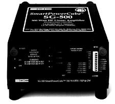 The amplifier I currently use is the SGC SG500. It has much better fault protection than any currently available mobile amp. It has RF keying, which I don't use because of the extra keydown delay (≈100ms). The fact the key up delay isn't adjustable adds insult.
Probably its best feature is automatic band selection. I've tried every scheme you can think of to automate band selection. No matter how you do it, no matter how careful you are, sooner or later you'll transmit into the wrong bandpass filter with predictable results. Use the automatic feature, and that just can't happen. The only drawback is a slight delay (≈250 ms) on first keydown , and about 100 ms thereafter. By the way, the SG500 is the only (legacy) mobile amplifier which can be keyed directly (no interface) by most Icom and Yaesu transceivers.
As bullet proof as it is, if you use one of these amps, and it is mounted in the trunk, do yourself a favor—buy the extra cost fan kit. With an adequate power feed (and the fan kit), the amp will keydown forever at 500 watts out! This sort of capability doesn't come cheap, but quality never does. I own two of them, and one has 1,000+ hours of mobile keydown time (SSB) without a hitch! It is a good thing I own two, as the SG500 has been out of production for early 4 years.
I should mention, that the SG500 is almost still-born. Toshiba, the maker of the 2SC2279s the SG500 uses, stopped production which limited SGC from producing more of the product. Similar transistors from other manufacturers with the same part number, will not work without modifications to the amplifier. While it is rumored that SGC is testing pre-production units using a new transistor type, no concrete information is available. This is unfortunate, as the SG500 has been (without doubt) the best designed mobile amplifier to date.
Running more than 500 watts out can be done. I know several people who use an ALS-1300 mobile, powered by a variety of subsystems. The aforementioned 4CX250 home brew amp would easily run full legal limit. But once you get past 500 PEP, things start to get rather difficult. One limiting factor is the antenna. Contrary to published specs, precious few HF mobile antennas will actually handle 1,500 watts PEP, much less a dead carrier, unless they're poorly mounted (having a dominance of ground losses). But that is not the only limiting factor. All on-board electronics are vigorously tested to assure their survival in high RF energy fields. However, when the wiring between the various on-board devices is exposed to high levels of RF, the signal paths can be disrupted causing all manner of glitches. Some of these glitches (ABS controls for example) can be dangerous to your health in ways RF never could on its own!
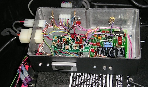 I typically don't leave things alone, as I'm always looking to make things easier, less distracting, and above all, reliable and easy to work on. In that vain, I remounted my BetterRF TCSC inside a large Hammond cast aluminum box (available from Mouser and DigiKey), along with some extra goodies, and bolted the assembly to the top of the amplifier using existing screws.
All of the various controls, and low-current cabling connects through this box. This includes the amplifier's control wiring, the cable from the remote switch up front, the CI-V and accessory socket cables (PTT & ALC), and the power out to the antenna. The hour meter measures the up-time for the amplifier. There are three LEDs. One indicating power to the box, a bicolor indicating power out polarity to the antenna, and an ALC indicator. These are used for trouble shooting, should the need arise. Out of view is an 18 volt, 50 watt Zener used to clamp any transients, and several bypass capacitors for the incoming power. These are used to protect the meters (voltage & hour). 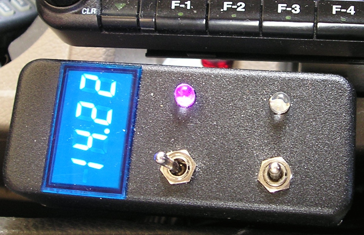
The small Hammond box in the right photo contains switches which control the amplifier, video to the Navi (see Video Display below), and remote coaxial relay (not shown in the photos) which switches over to the 6 meter loop when needed. The voltmeter is a two wire Datel unit. All of the cabling is straight forward, and has Molex connectors on both ends to ease installation and removal.
Just out of sight below the 3 amp ATC fuse in the left photo, is one of two 120 amp Anderson Powerpole. One supplies the power from the front battery, and the other from the second trunk-mounted battery. All connections are fused with 60 amp Maxifuses.
The IC-7000's main chassis is bolted to the amplifier's fan assembly (it is behind, and below the black box). Since all of the wiring is connectorized, the whole assembly can be removed in a matter of minutes when required.
Incidentally, the BetterRF Company has ceased operation. This leaves only the TurboTuner-2, MFJ, TuneMatic®, and West Mountain Radio making automatic controllers.
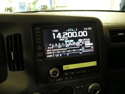 TVandNav2Go makes a video interface for almost every factory-installed navigation system ever made. It is housed in a small metal box, about 1 x 3 x 4 inches, and sells for $250. Most of the competition is at least $100 more. The instructions are rather lame, however it is easy to install. If you have an Icom IC-7000, this is a great addition worth the price of admission, if for no other reason than to reduce distraction.
From a personal standpoint, I'm of the opinion that Icom laid an egg by not including video out on the IC-7100. This ignores the inane idea that a touch-screen transceiver was a good idea for a mobile installation. Perhaps no one operates mobile in Japan these days.
By the way, the TVandNav2Go has an additional video input (Video 2), commonly used for a backup camera. It too can be switched, and it also takes precedence over the Video 1 input. Using it for a DVD player is contrary to most local laws, so if you do, you're on your own.
All of us are on a learning curve, and it is a poor day when we don't learn something useful. One of the first lessons I learned after becoming an amateur radio operator, was the absolute importance of having a good antenna. This is especially true for mobile operation. The HyGain 15 meter antenna I spoke about above, is a very good example.
It came with rather large brass end caps, which held an outer fiberglass cover in place. I broke that outer cover by hitting a low-hanging limb. I simply removed the end caps and cover entirely. Suddenly, my near perfect (so I thought) antenna would no longer work properly. This started me on a quest to find out why this was so. It was, and still is, the impetus behind my fascination with mobile operation in general, and mobile antennas specifically. For more information, read the Antenna Efficiency article.
By the way, the reason the antenna didn't work correctly is simply this. The end caps not only reduced the Q of the coil, they also change its inductance. This required a change in the length of the whip, to bring the antenna back into resonance.