![]()
Contents:Basics; Ground Losses; Radiation Resistance; Coil Losses; Calculating Efficiency; Bandwidth Notes;
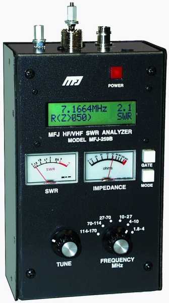 Antenna efficiency is an elusive quantity, which is difficult to qualify. We can calculate it easily (close) enough, if we know three things: What the ground losses are, along with the radiation resistance and coil Q. Unfortunately, we don't know any of these values with any certainty, although we can use an antenna analyzer to measure their total series value—the input impedance in other words. Since these values are in series with one another, if we change one, it has an effect on the others. A good example of the complexity herein, is the addition of a cap hat.
A cap hat adds capacitance to that portion (length) of the antenna above the loading coil. No matter where it is placed along that length, it adds the same amount of capacitance. This will cause the input impedance to increase. However, the change in the input impedance may be due to an increase in the radiation resistance, or to additional resistive (Q) losses in the coil, depending on where along the length the cap hat is installed.
It should be apparent that accurately calculating efficiency can not be done with simple test tools, or anecdotal formulas commonly found on the internet. However, we can get a lot closer if we know a few basic facts about the input impedance (total losses). It should be mentioned at this point, that there are other losses combined with the input impedance. Stray capacitance and conductor losses are the main ones. Since they're usually (not always) small compared to the other losses, we can just ignore them.
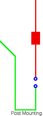
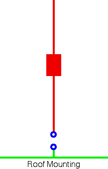 Ground losses (Rg) dominate the efficiency equation, and keeping them low is a worthy exercise. Toward that goal, the most important consideration is proper Antenna Mounting. In other words, It is the metal mass directly under the antenna, not what's along side, that counts! The drawing at right depicts the correct mounting style. The one lower left depicts an incorrectly mounting style. Further, a ground strap to the nearest hard point is not a substitute for proper mounting! In fact, excessive and/or incorrect grounding can cause ground loops to occur, often masquerading as RFI!
 The average recognized figure for ground loss, varies from 10 to 2 ohms (80 through 10 meters). It may be considerably higher than this value, but never lower! Lack of proper bonding, incorrect or missing control line chokes, poor mounting techniques, poor mounting locations, and incorrectly terminated coax feeds, all play a part. And, since ground losses are proportional to the square of the field intensity, if you double the field intensity, the power losses increase by four times! This in the main reason ground losses should be kept as low as possible, especially when using physically short (mobile) antennas.
We should also remember that RF current must return to its source. When we mount an antenna low, more of the return current is forced to flow through the lossy surface under the vehicle, rather than the body of the vehicle.
 Here is another way to look at the issue. Wherever the coax connects to the antenna is where the ground plane must begin. In other words, if there isn't a mass of metal directly under this point, then ground plane losses increase. Excessive ground loss also increases the level of RF flowing over the outside of the coax (common mode currents), and on what ever control lines are present. This is an exceptionally critical point if you're using, or planning to use, a computerized Antenna Controller.
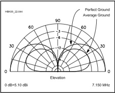
Ground losses also affect the low angle radiation. At depicted in the chart at right, the mean takeoff angle (the angle of maximum radiation, ≈27°) isn't affected by ground losses. However, the amount of power radiated at any given angle does change, especially at the lower angles (<15°). Thus, we have yet another reason to minimize ground losses, by placing as much metal mass (directly) under the antenna as possible.
Lastly, there are cases where ground losses takes a back seat to coil losses. Short, stubby antennas are an example. It is not uncommon for the coil losses in these antennas, to be 2 or 3 times the ground loss. This magnitude of coil loss is also the reason short, stubby antennas don't need matching.
 The only good loss is imaginary, and that's Radiation Resistance (Rr). It is imaginary in that it doesn't exist as a physical part of an antenna in the same sense as a loading coil, whip, or mast. It is, however, real with respect to mathematical calculations.
In simple terms, Rr is a function of the effective electrical length (not the physical length), and how the current flows over that length. Thus, the longer the antenna's electrical length, the higher the Rr will be. It should be noted that the rate of change is a square law function. That is to say, a 9 foot antenna will have about twice the Rr of a 6 foot antenna. A 12 foot one will have four times the Rr of a 6 foot one. Rr may be as low as .2 ohms (80 meters), to about 36 ohms (full 1/4 wave on 10 meters).
As noted above, another way to increase the radiation resistance of an antenna is to use a cap hat. Properly designed and implemented, they increase the effective electrical length, and they raise the current node. It is possible to increase the Rr by a factor of 4, particularly on the lower bands. The key words here are, properly designed and implemented. Done incorrectly, and they will have the opposite effect.
Lastly, for any given electrical length of an antenna, the radiation resistance (Rr) it exhibits, is the sum of the total power radiated by the antenna, divided by the square of net current causing the radiation. As noted, it is a factor of the effective electrical length of the antenna, so we must lengthen the antenna (electrically and/or physically) to increase it. Obviously there is a limit to how long physically an HF mobile antenna can be, with 11 to 14 feet about the maximum (suburban, versus rural). If you live east of the Appalachians, perhaps just 8 feet. Again, the increase in Rr (when electrical length is increased) is due to the current node (point of maximum antenna current) being modified. If you need more information on this, go here.
To reiterate, the radiation resistance is affected by the ground losses present, as well as the coil Q.
Coil loss (Rc) is one of the most misunderstood aspects of mobile antennas. Part of the misunderstanding deals with the term Q, which stands for Quality. It is determined by dividing the inductive reactance in ohms, by the resistive losses in the coil in ohms, at the operating frequency. Under laboratory conditions, it is possible to obtain coil Qs in the 800 to 1,000 range. However, in the real world of mobile loading coils, it is difficult to obtain Qs over 250 when mounted as part of an antenna. Even this takes good construction practices.
 With the possible exception of 10 meters, perhaps 12 meters, and sometimes 15 meters, all HF mobile antennas incorporate a loading coil. Although it adds physical length to the antenna, it does not increase the electrical length except in very special cases (long, skinny, linear loading is an example). And, the current flow within the coil is always uniform, except in the special case noted. In other words, an antenna loading coil is a lumped constant. On-line sources which state that a loading coil replaces a given physical length of an antenna, are in error!
The reason we need a loading coil is simply this. The input impedance of any antenna shorter than a 1/4 wave length will exhibit capacitive reactance (-j). In order to cancel out this negative reactance, we incorporate a loading coil with equal, but opposite reactance (+j). The shorter the antenna (in terms of wavelength), the larger the coil's reactance must be, along with a corresponding increase in coil losses, all else being equal. The table (courtesy of the ARRL) illustrates the effects. Note the efficiency levels. Incidentally, the inductances given in the table are for based-loaded antennas, and do not take ground losses into account.
Excessive distributed coil capacitance also reduces coil Q. A good example is the use of large end caps and/or metal shorting plungers. Another is antenna mounting locations which place the coil too close to body work (shunt capacitance). The worse case is mounting a cap hat directly atop the coil, rather than at the very top of the antenna where it belongs.
We should also dispel the notion that large diameter coils (>3.5" OD) have higher Q ratings, when in fact the opposite is true. The reason is, large coils have more distributed capacitance than smaller ones, all else being equal. They also have lower self-resonance point making them very lossy at the higher frequencies. The optimal size and construction? About 3 inches OD, 6 TPI, using #10 silver plated wire.
You cannot measure a coil's Q once it's assembled within the antenna. So, it isn't uncommon for antenna manufacturers to publish their static (bench) Q measurements, and apply them to the assembled antenna. With this in mind, if a manufacturer claims their assembled coil Q is over 300, be very leery!
There is no easy, cut and dried, measure of antenna efficiency. Bandwidth, number of DX contacts worked, coil type, antenna type, mounting type, antenna shootouts, make, brand, matching method, cap hat, nil, not, nix, nothing! Even modeling can give you a false impression. So, the question remains, how do you know if it is efficient?
Efficiency can be calculated (not exactly, but close enough) if all we know the three Rs (Rr, Rc, and Rg) values. All we have to do is add these factors together to get Rt (Rr+Rc+Rg=Rt), then divide Rr by Rt. For an average 8 foot antenna mounted on an average vehicle, and using an estimated ground losses, the efficiency ranges between .2% on 80 meters to maybe 80% on 10 meters. These figures are based on data taken from Chapter 16 of the ARRL Antenna handbook. By the way, if you want to know just how important coil Q is, calculate the efficiency differences between the figures for coil Qs of 50, and 300. If you prefer to use dB as a reference, the formulas is 10 log (Rr/Rt).
The aforementioned method assumes we know the radiation resistance. We don't, at least with certainty, even if we go through the necessary formula machinations listed in the ARRL Antenna Handbook. However, there is a way to get close, or at least as close as we need to be.
In the Technical Correspondence section of the September 2006 issue of QST (page 57), are a few paragraphs written by Dr. Jack Belrose, VE2CV. Jack explains how to use an antenna analyzer and EZNEC to calculate the efficiency of a mobile antenna. The basic premise is to compare the measured input impedance of your mobile antenna, compare it to the modeled impedance given by EZNEC, and then adjusting the coil Q (resistive loss) until the two impedances (measured and calculated) equal. Then reading the programs calculated radiation efficiency.
There are a couple of things to remember when using this method. First, the analyzer's frequency must be adjusted until the reactive component is zero (X=Ø), and not for the lowest SWR! Then, and only then, will the resistive value be correct (within tolerances). The measurement needs to be made without any matching devices attached. In other words, we need to know the actual input impedance, not a transformed one. And as mentioned above, the measurement must be taken as close to the antenna as possible, and not at the transceiver end of the feed line!
Depending on the program used (Nec, EZNEC Pro, etc.) the spread of calculated efficiencies may be as much as ±10%. If in doubt, always choose the worse case scenario, as the best case usually assumes facts not in evidence. Lastly, just because your efficiency is great on 20 meters, is no indication what it will be on some other band, higher or lower. In fact, the higher bands may have greater loss due to capacitive coupling.
Just for the record, EZNEC, and most of the other numeric electromagnetic coding engines, are marvelous programs. They allow expert, and neophyte alike, to model all-manner of antenna parameters. However, the results are dependent on the data provided! For example, leaving out the feed line when doing an analysis will skew the results. Another common error is miscalculating ground losses. Therefore, assuming and quoting the results verbatim without a thorough understanding of how antennas behave (especially mobile ones), often leads users astray. In other words, these applications are a tool, not a panacea!
There is another Q factor we have to contend with, and that is the Q of the antenna as a system. The Q of a short HF mobile antenna is directly related to the coil's Q, the coil's distributed capacitance, the capacitance of that part of the antenna above the coil, any capacitance shunting the coil, where in the antenna the coil is located (base?, center?), shunt capacitive losses, the overall (effective) length of the antenna, the ground losses, and the other resistive losses including radiation resistance. You might notice these are the same losses we deal with in maximizing efficiency. In short, while we strive to increase efficiency, we also increase the antenna system's Q which tends to reduce the effective bandwidth of the antenna. In other words, to increase efficiency we have to lower the resistive losses, or increase radiation resistance, or both. You can do both to a point, but there are diminishing returns with respect to cost, complexity, and of course physical size.
While it is common to relate (usable) bandwidth to the points above and below resonance where the SWR reaches 2:1, it isn't definitive. The reason is, you can have a wide bandwidth antenna that is very efficient. You can also have a very narrow banded one that's inefficient. So, why is bandwidth important? It really isn't much of a concern on 20 meters or above, but below 20 meters it is. Put another way, the bandwidth of an 20 meter antenna of reasonable quality will be about 150 kHz. The bandwidth of a similar quality antenna on 80 meters may be just 10 to 15 kHz. Again, don't assume your antenna is efficient just because the bandwidth is narrow.
Bandwidth is also dependent on the amount of capacitance located above the loading coil. All else being equal, an antenna with a large (properly mounted) cap hat will have a wider bandwidth, and higher efficiency, than one without. This is opposed to the common view about bandwidth. Some amateurs incorrectly assume that inexpensive, low Q antennas are superior to some higher priced ones. The false assumption is, they don't have to retune their antenna as often, so it is got to be better. Adding insult, a few misguided manufacturers tout their products extended bandwidths as an advantage. Both of these premises are false.
Besides using a tuner, another way to extend the bandwidth is to use a shorted coax stub across the antenna terminals. Selecting the correct length will not only match the antenna's input impedance to the feed line, its reactance is exactly opposite the antenna's reactance with any given change in frequency. Thus the 2:1 bandwidth increases (typically 30% to 50%). While the trick works well for a single band antenna (a different stub is required for each band), it is not a good solution for a remotely tuned antenna.
Lastly, there is a formula circulating the Internet which states that antenna Q is equal to 360 times the frequency in MHz, divided by the 2:1 VSWR bandwidth in kHz. One has to assume they mean antenna system Q, but that's not a given. While this formula might give you a comparison between antenna A and antenna B (all else being equal), the actual Q of the antenna (system or otherwise) requires a textbook-full of formulas, and a lot more information than just the 2:1 bandwidth! Fact is, this formula is no more specific than the number of DX contacts a specific antenna garnered.