![]()
Contents: Basics; Foreword On Mounting; Mag Mounts; Ballmounts; Bed, Clamp, Clip, Lip, Seam, and Trunk Mounts; Foldover Mounts; Quick Disconnects; Home Brew Mounts; Pocket Mounts; Post Mounts; Springs & Guys; Trailer Hitch Mounts; Whips & Masts; Odd & Ends;
While reading this section, it is important to remember, that modern steel or aluminum bodied vehicles, use very thin material for all body panels. This all but eliminates the use of mounts which rely of the strength of the body panels. It is possible to internally brace body mounts, however this usually requires extensive fabrication and is not recommended.
A decent quality (read that as efficient) HF mobile antenna is not an inexpensive commodity, and may cost upwards of $1,200 (although lessor quality ones are about half this amount). Assuming you spent this much for yours, why would you mount it in an inefficient manner? Yet, this is the case 90% of the time. It pays to remember, that Antenna Efficiency is a balancing act between the various system losses. Even one ohm of additional (resistive) loss (anywhere in the system) can make a significant difference in the signal to noise ratio, on both ends of the contact. Thus the antenna should be attached in such a way to maximize what little ground plane a vehicle represents. The key phrase here is, it is the metal mass directly under the antenna, not what's along side that counts! More on this aspect below.
Another often overlooked requirement is which side of the vehicle the antenna should be mounted on. Here in America, we drive on the right and steer from the left, so we should choose the left side. This can be very important especially when you live in an area with low bridges and overhanging trees, as there is more clearance towards the center of the street. Further, it is easier to see the antenna in the rear view as opposed to craning your neck. It is also less likely to be "twanged" when you're parallel parked. If you've chosen front mounting as a lot of folks who pull trailers do, then it should be mounted to the right into your peripheral vision to avoid distraction.
Minivans, SUVs, RVs, Jeeps, station wagons, crossovers, and plastic-skinned vehicles present a special case. Except for front mounting, the body of these vehicles shadow a large portion of the antenna. This causes tuning problems, and reduces efficiency which is already poor at best. If shadowing cannot be avoided, then make sure the coil is as far away from sheet metal as possible to minimize coil losses.
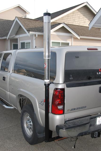 This is a good point to mention pickup trucks. Almost everyone mounts their antenna atop a bed box, or a mounting bar, and in the dead center! Well, if you garage your vehicle, this requires a quick disconnect on the whip or cap hat. Mounted dead center, you have to get into the bed to remove it. It behooves pickup owners to mount the antenna close to one end of the mounting area because of this fact.
If you have a bed cap, you might consider the method K7KKP used, which also works well on vans and SUVs. Enlarge the photo by clicking, and note the plate attached between the top of the post and the bottom of the antenna. This plate establishes the ground plane at the base of the antenna, rather than the post's support structure. There are additional photos of the setup in the Photo Gallery under his call.
Maximizing what little ground plane a vehicle offers, is a worthwhile endeavor. Bonding is part of the solution. The aforementioned shadowing is also important, and there's another one, mounting height. As we raise an HF antenna from low on the bumper towards the roof, the resonance frequency decreases. Part of this decrease is due to a decrease in ground losses. However, capacitive coupling between the antenna, and the surface under the vehicle causes most of the effect. The change in resonance is typically between 1%, and 3%. These factors will also cause a decrease in the input impedance, which is a good thing even though the unmatched SWR might increase.
Ground loss is in series with the other antenna losses, including radiation resistance, and it is these combined losses which make up the input impedance. Therefore, any increase or decrease in one or more of the other losses, will also effect ground loss, and the current which flows through that ground loss. As a result, you cannot assume that some change in one (or more) of the other losses making up the input impedance is a positive (or negative) one, without considering all of the other factors as well—the system as it were.
There is a drawback to increased height. From a safety (and practical standpoint), the maximum height is from 11 feet to 16 feet depending on your area of the country. Here in the desert southwest, I have little trouble with the tip of my antenna extending to 16 feet. If I lived in the New England area, I'd be hard pressed with just 11 or 12 feet.
Most HF mobile antennas are already length-compromised and shortening them isn't really a viable option if you're seeking good performance. You could use a cap hat (capacity hat) which will allow you to shorten the antenna and maintain some level of efficiency, but you have the extra wind load and complexity to contend with. This height vs. efficiency vs. practicality conundrum leads to an obvious compromise. How much of a compromise depends on the type of antenna you use, and where you choose to mount it. The only rule of thumb is, mount it as high as your terrain and antenna length will allow up to the point of striking low-hanging wires, branches, bridges, and parking garages.
There are many different manufacturers, lengths, and styles of remotely tuned antennas, but they all have one thing in common; they're difficult to mount. They require both a coax feed and a power feed, and no one makes a universal mount for them. Due to the extra weight compared to a nominal monoband antenna, the mounting medium must be extra strong. As a result, most folks opt for a bumper or trailer hitch mount which reduces system efficiency.
 The current rage in HF mobile antennas, are the various short, and stubby varieties. Their short overall length reduces radiation resistance, and increases resistive coil losses as well (low Q factors). Most have short masts making it difficult to get the coil clear of the bodywork. With a large mass of metal close to the coil, they are much more of a compromise than most folks realize. If that wasn't enough, they're universally sold with K400 style clip mounts.
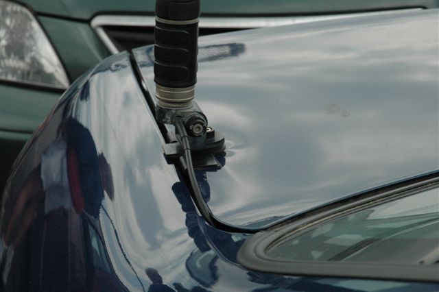
A lot of misinformed folks use clip and mag mounts because they're convinced they don't depreciate the value of their vehicle. Look closely at the left photo (click to enlarge). While a drilled hole can be easily plugged, and go unnoticed, there is no way this type of damage can be ignored. If you want a different perspective, read this PDF. There is another problem associated with mounting antennas on hatches, and rear doors. Most hatches (and doors) have defroster grid wires, a CMHSL, and sometimes even wipers. Since these hatches offer a poor ground return for the RF current, a goodly portion of that current ends up being induced into the vehicle's wiring. This fact causes all manner of RFI problems, and because the wiring is difficult to get to, it is nearly impossible to use ferrite material to overcome the problem.
There is yet another issue with respect to clip mounts. Motor lead and/or coax choke must be mounted outside the vehicle to minimize RFI. Due to the way clip mounts are designed, choking the motor leads is difficult enough, but choking the coax is nearly impossible.
There is one very important caveat to keep in mind. The roof of a vehicle is a very good place to mount an antenna. However, more and more new vehicles are coming equipped with side curtain SRS devices (airbags). Some of them are mounted along the edges of the headliner including the rear seat area if there is one. The wiring to these devices may be routed through any one (or more) of the roof pillars. Extra care is required when installing antennas in vehicles so equipped. If you are the least bit apprehensive about your installation, seek professional help from your dealer or a qualified installer.
The type of mount you use is dictated by several conditions. The main one centers around one's feelings about drilling holes in a vehicle's body. While there are ways around the issue, they often require fabricating special brackets—apparently a lost art! This fact is why so many newcomers to the hobby opt for short, stubby antennas to avoid the issue. However, short, stubby antennas have their own set of issues, not the least of which is poor efficiency, and excessive common mode.
The size, weight, and length of the antenna, and to a lessor degree aesthetics and spousal approval are also issues which need to be considered. Heavy antennas like the Scorpion 680, require additional thought and preparation if they're extra efficiency is to be exploited. Overall length is important too, especially if your neck-of-the-woods is highly forested. If it is, then cap hats are a viable alternative to length, but only if you're willing to opt for a well-mounted, heavy and sturdy antenna!
Let us face a fact of life; mobile antennas aren't what most folks would call pretty. Some in fact, are just plain ugly! Your spouse may not like what he/she sees, but remember this; form follows function. So if you opt for an antenna that looks pretty, doesn't require drilling holes, you're going to be less than satisfied in the long run.
If you've read the Antenna Efficiency article, you'd know why minimizing ground loss is so important. But if you're thinking a ground strap to the nearest hard point on your vehicle will negate this situation, you're wrong!
There are many reasons to permanently install any mobile antenna. Aside from maximizing performance by minimizing ground and shunt capacitance losses, there is the safety issue should the antenna come unstuck. Further, some insurance companies will not cover antennas which are not permanently installed. These facts preclude the use of mag mounted antennas.
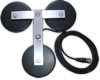 The one shown in the right photo is a typical unit. When they're demonstrated in retail outlets, they're stuck to a thick chunk of metal. Since the amount of sticking force is reliant on the thickness of the material it is stuck to, the actual force will be much less when it is sitting atop your vehicle. It doesn't make much difference how many magnets they have, or how big they are. The fact remains they will become flying missiles in the event of a crash.
There are two more problems users should be aware of. First, they collect road debris (mainly metallic brake dust) which eventually gets between the magnet and the sheet metal. Secondly, the base cover, usually a rubberized plastic, has an affinity for clear coat vehicle finishes. It is a given that the surface under the mag mount will become both scratched and/or discolored over time. In some cases, less than a week! The bottom line is, if you have to resort to a mag mount for your antenna, you haven't thought long enough about other, safer, more efficient, mounting methods.
Posters to several on-line forums suggest removing mag mounts from time to time to wipe off the collected debris to keep them from damaging the painted surface their stuck to. This really doesn't help much. The particles themselves are almost colloidal in size, and they actually penetrate the pores of the material making up the mag mount, as well as the paint under the mag mount. Moisture mixes with these minute-sized particles, and other pollutants, forming a mild acid (typically sulfuric). It is the acid which discolors the paint, not necessarily the rusting particles of brake dust. If you think yours is clean, here's a simple test. Pull the magnet across a piece of plate glass, and see what happens.
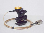
 Nowadays, most ballmounts aren't worth the effort, and the one in the right photo is worst of the lot. I don't know the actual manufacturer, but Motorola®, Wilson®, Antenna Specialists®, Hustler®, and others currently sell the exact same one, shown at right. It consists of two, stamped, stainless steel half spheres, separated with a rolled steel ferrule, replete with a cheap plastic insulator and thin backing plate. Note the teeth at the bottom of the ball. They're suppose to keep it from rotating. They don't. If you tighten the cross bolt enough to hold the antenna upright, the ferrule will unroll, and your antenna will flop over. If your antenna weights more than 2 pounds, forget about this mount! Worse, the various pot metal ones found in CB shops won't reliably support a Hamstick®.
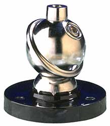
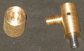
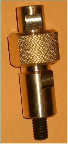
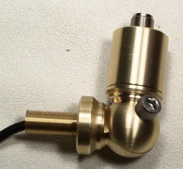 There is one all brass ballmount available (left photo) made by Breedlove Machine Shop. They come with and without the quick disconnect shown. The QD is also available as a stand-alone unit. The ball itself is pinned to prevent rotation, making for a very secure fit. The unit pictured in the upper left of the photo, is an SO-239 built as part of the center stud attachment bolt. This makes the coax connection very secure.
They also make a ballmount which has an SO239 connector, fed with a short piece of RG58U. It is ideal for most import antennas which use this type of mounting. It also comes with a large backing plate (not shown).
Bed, Clamp, Clip, Lip, Seam, & Trunk Mounts
 There are several things to keep in mind when using any non-permanent mounts, no matter how they attach. First, it is no better than the vehicle sub-structure it is clamped to. A typical example is a roof rack. Most are not DC grounded to the body of the vehicle. Even when they are they still represent a poor ground plane even at UHF.
Seam mounts (often called L-brackets or gap-mounts) are almost a thing of the past due in part to minimal seam clearances on modern vehicles. They may still be used in some cases (hood area), but some provision must be used to allow clearance for the coax cable—a difficult task.
Clamp mounts like the K400 shown at right might save you from drilling a (visible) hole in sheet metal, but they can still cause body damage, as the above photo of the K400 depicts. Since the return path for the coax relies on the integrity of the hinges, and the mounting set screws, they also increases ground losses. Adding insult, most clip mounts come equipped with a preinstalled RG174U coax assembly, although some use RG58A. The cable is usually 10 feet long (3 meters actually). At 30 MHz, the loss averages about .5 dB, and increase to about 1 dB at 150 MHz (≈2 meters). At 450 MHz (70 cm) the loss is almost 4 dB. Add in some ground loss, some impedance mismatch, and the total loss attributed to a clip mount can easily double the aforementioned figures.
 Almost every screwdriver manufacturer supplies a "C" clamp mount like the Tarheel one shown at left. The supplied insulator isn't very robust no matter the brand. On other manufacturer's models, the top clamp is just a U-bolt, and a piece of rubber or plastic is supplied to wrap around the mast, and act as an insulator. During inclement weather, these mounting schemes can cause problems as they have a tendency to arc over. One solution is to coat the assembly with high voltage lacquer available at most hardware and home improvement stores. One thing you don't want to do, is coat them with car polish due to its conductivity!
The clamp mount shown at left is a new entry from Breedlove. It was made to clamp over the front of a pickup bed, and is small enough to slip under most bed covers, replacing the insulation. You can go to their web site for more information and pricing. Note the SO239. This makes interconnecting really easy.
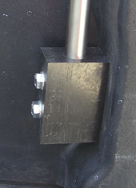
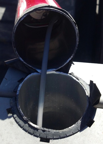 The photo shows a broken screwdriver antenna which was mounted using a U bracket similar to the one shown at left. This antenna was mounted on a pickup truck which sees a lot of off road activity. Eventually, the metal fatigued to the point where wind loading was enough to cause the mast to fail as shown (click to enlarge). If your driving style includes off road work, and you use a screwdriver mounted with a U bracket, it behooves you to do two things. One is to disassemble the antenna, and slide in a close-fit aluminum tube to strengthen the area near the top of the bracket. An outer sleeve/insulator might also be an necessary addition depending on the specific antenna in question.
 Foldover mounts, like the Breedlove one shown left, have been with us for some time, although they're not a fit for all installations. In some cases, a quick disconnect (shown below) is a better choice. Obviously, the foldover shown won't hold much more than just the whip.
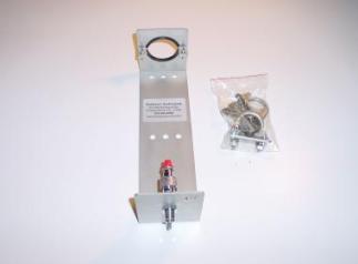
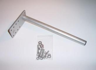
Heretofore, no one has made a foldover sturdy enough to support a decent-sized screwdriver antenna. Those days are over! Breedlove has introduce their new, Scorpion super-duty foldover mount, shown right, capable of supporting antennas as large as 20 pounds! It's machined out of 2.5 inch square aluminum, and accepts a 3/4x10 mounting stud. While designed specifically for the Scorpion, it is adaptable to antennas which use the standard 3/4x24 thread style, simply by using a slip-in adapter. If your installation requires a foldover, or you need to tilt your antenna back, this mount is the answer.
 Hustler, Breedlove Machine Shop, and others sell whip QD units. I prefer the Breedlove screw-on ones as shown at right, because they're more secure, and make better electrical contact. The bayoneted ones as supplied by Hustler, have a tendency to become loose over time, especially if they are used at the bottom of the antenna. If you're using a QD, and you're having intermittent receive issues, the QD is the first place to look.
Some are plated brass, and some are stainless steel. The few that are made of pot metal aren't worth the effort. Breedlove has a new combination fold over/quick disconnect that is quite clever in design (shown below, left). I've never been enamored with foldovers, especially masts, due to intermittent issues. However, the Breedlove unit screws together firmly, and there is less flex as well.
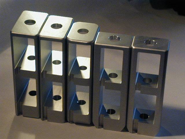
 When you just cannot find what you need or want, one way out is to home brew your own. The mounts shown here are two of many I have constructed from Delrin® plastic. It is a little difficult to see in these photos (there are high res photos of them in the Photo Gallery), but the mounts were drilled to mate with existing holes in the bed rail used to support the tie down cleats.
The nice thing about Delrin®, the natural color is RF transparent up to the SHF region. The black, fiberglass reinforced material shown here is good to about 1 GHz. The main drawback, is cost. Current prices for 1 inch material is about $100 per square foot. The top and bottom mounts shown here are each made up of one, 1.25 inch thick, by 6.25 inch pieces. They were part of a 25 pound box of Delrin®remnants I purchased from Professional Plastics for $58. By the way, they carry all kinds of remnants, including Nylon®and Noryl®, and they tend to be less expensive than other on-line suppliers.
 Delrin®can be sawed, drilled, tapped, planed, and sanded with standard hand tools. In some cases, I have press fit ferrules into the material, but this really isn't necessary.
Delrin®is very slick. In fact, it is almost as slick as Teflon®. Therefore you have to be careful when you drill and tap it. If you need to drill holes larger than 3/8 inch or so, use a Forstner or spade bit. Make sure you clamp your work to keep it from binding or snatching. Also, take your time, and go slow to avoid melting the material.
The mount shown at left holds an M-Squared 6 meter squalo. Like the home brew mounts above, it uses existing threaded holes normally used to bolt down the cargo cleats. This makes the mounts very robust. The bolts are 1.25 mm and in whatever length you need, but the exposed threads shouldn't be longer than a 1/2 inch. Incidentally, the spacing is approximately 1.1 inches on centers, but there is some variation. I used a 3/8 inch drill bit for the bolt holes which allowed for a little slop in the hole spacing. You'll also need a T50 Torx® bit to remove the existing cleat bolts.
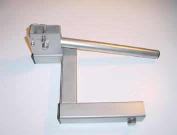
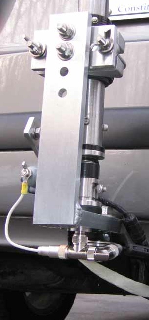
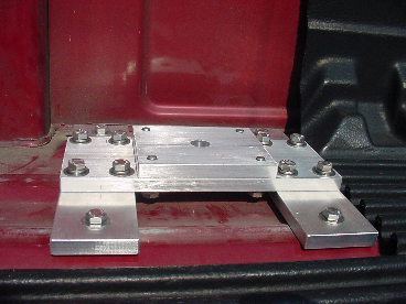 The mount shown at right was custom-made for a Scorpion 680 by Bennie Bolin, W4XTL, and now available for purchase from Breedlove. It is designed for installation of any HF mobile antenna to the floor of a pick up bed. To say it is sturdy, is an understatement. Unseen are the two plates which attach under the bed, reminiscent of a 5th wheel mount. It certainly shows what can be done by applying a little patience. A full-res copy is in the Photo Gallery under Antenna Mounts.
If you need a ground return, here's a couple of suggestions. Apply some NoOx®or similar anti-corrosive on the bolt threads, and use star washers under heads, as some of the tie down holes are exposed to the elements. Honda's recommendation is to torque the cleat bolts to 16 foot pounds which should be followed, as you certainly don't want to strip the threads.
Metric bolts of a given thread size don't always have the same sized head. For some unknown reason, the longer the bolt the smaller the head size. The ones seen in the photos have 11, 12, or 13 mm heads. Knowing this should save you time looking for the right wrench!
 Breedlove Machine Shop makes a variety stake pocket mounts. The one shown at left was designed for the Border Patrol, and will slip under most bed covers. They're adaptable to most antenna mounting styles, and allow the coax to feed through the bottom of the stake pocket. One very interesting one is designed to for stake pockets which don't have side rails. It is shown above left. Visit their web site for more information.
There are others who make stake pocket mounts. However, most of them utilize a rubber block that is squeezed by a mounting bolt. Thus they rely on friction to hold them in place. I wouldn't trust them to hold anything more than a small VHF antenna.
GeoTool® is back in business! As you can see from the right photo, they're well made, and available in a variety of configuration. Check out their web site for moe details.
 Post mounts like the Tarheel one shown at left, are very handy for mounting antennas on flat surfaces like a truck bed or side rail. However, extending them to place the antenna higher is counter productive, as doing so greatly increases the ground losses.
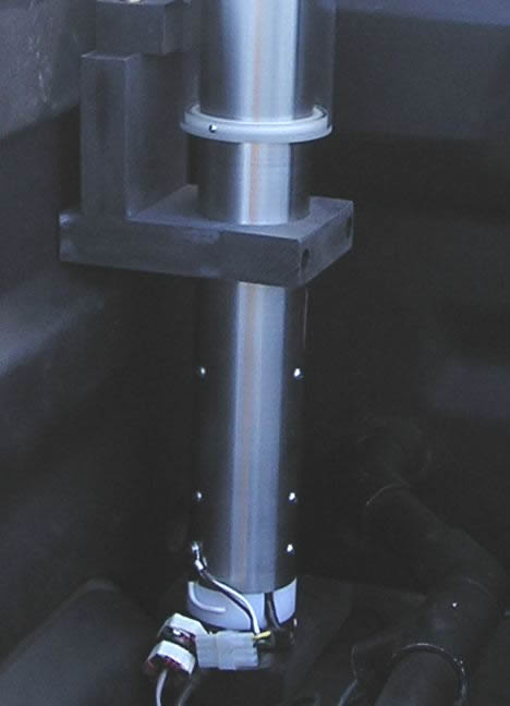
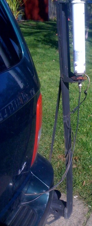
For example, It is not uncommon to see antennas mounted atop extended posts, like the one shown at right. The consensus of opinion is, that by raising the antenna to the top of the post will increase efficiency by unshadowing the mast and coil. As alluded to above (Far Removed Ground Planes), this premise is incorrect as the post raises the antenna above its ground plane, hence increasing losses.
To be honest here, this particular Tarheel post is a variation of the foldover one shown below right. The antenna bracket clamps to this post with U-bolts. The post mount from MFJ is similar, but has a one inch pipe thread at the top which screws into the base of the antenna.
If you click on the right photo to enlarge it, you'll also notice there is no motor lead choke, and no coax choke. Due to the mounting style and the short, stubby antenna used, common mode current is a given. Not only that, if RF can get out via common mode, RF noise can get in as well, which increases the receive noise level precipitously.
When using a body-mounted ballmount, springs are virtually a prerequisite. The spring helps prevent damage from low-hanging branches, and the ever-present antenna twangers who cannot resist playing with your favorite toy. Most amateurs don't use springs at the base of their antenna as they believe is causes the SWR to vary while underway. If this is the case, chances are you have your antenna mounted too low and/or too close to the body. The other misconception is the inner braid fails. I used an old HyGain heavy-duty unit I have owned for some 30+ years. The braid is still bright and shiny.
Although I've never guyed an HF mobile antenna, doing so has some safety benefits, and allows the use of a lighter spring. However, let me add this; guying is not a substitute for proper mounting! In other words, if you have to resort to guying to keep your antenna in place, you haven't properly installed your antenna!
Although fishing line seems to be the preferred medium for guying, I think it stretches too much. Phillystrand®is a better option. Choosing how to anchor one end to the body is a personal choice. On the antenna end it is best to attach the guy below the coil where the voltage is less. Remember one thing about guys. Regardless of the material you use, moisture can collect on it or in it. Transmitting when it is wet will net you a burned guy, high SWR, or both.
 If you plan on using a trailer hitch as an antenna mount, here's a suggestion. Have a second hitch ball receiver welded on the left end of the hitch. Then a short chunk of square tubing may be used as the actual mount, and it is easy to remove when necessary.
The trailer hitch receiver mount shown at right is one of several models sold by Tarheel. They are sturdily made, and will hold just about any mobile antenna. The mount slips into the hitch's receiver, and is secured by a bolt. This particular model features a folder over hinge, which might not be suitable for every installation. The one at left is by REP Designs.
One very important thing to remember about trailer hitch mounting; in terms of efficiency it is the least desirable location. And contrary to popular opinion, running a ground strap to the frame will not negate this fact. If you doubt this premise, read my Antenna Efficiency article. Further, due to the extra ground losses involved, you have to use extraordinary decoupling (large impedance chokes) to keep the RF off of the control and coax leads.
Whips, sometimes called stingers, are the flexible part of a mobile antenna extending from the top of the coil. Every amateur radio supplier stocks at least one brand. Typically sold without any ferrule, they vary in length from 24 inches to about 72 inches. Folks who need a longer whip usually use an 8 foot CB whip and cut it down if needed. If you do this, don't forget to add a corona ball.
Some amateurs use bronze welding rods for whips, and to build cap hats. Bronze works well, but it is easier to kink than stainless steel. You can purchase 17-7 stainless steel in several sizes from Speedy Metals. However, you might want to read this Antenna article section before deciding on 17-7 stainless steel.
If you need setscrews, and cannot find them at your local hardware store, Micro Fasteners is your best source.
Monoband antenna masts are available from DX Engineering®, Hustler®, Main Trading Company®, and MFJ®. There are a few things you should avoid doing with masts. First, is using a Quick-Disconnect at the base, no matter whose you use. The base is the point of maximum stress, and sooner or later the best of QDs will fail, especially the spring-loaded, bayoneted ones. Those with foldovers should be avoided at all costs! No matter how well they are made, it doesn't long before the foldover becomes loose with predictable results. Fact is, you often see examples of foldover Hustler® masts with a braided copper jumper across the hinge assembly to maintain a good connection.
Hustler® masts have another problem, in that the 3/8x24 studs are pressed into the aluminum. They eventually become loose, and in some cases fail altogether. In any case, you should use a base spring to minimize stress on the mast. If you notice any looseness (on this or any other mobile antenna), replace or tighten the part(s) before they come off while you're driving down the freeway! Incidentally, over tightening exacerbates the issue.
If you'd like to make your own mast, here's a site with instructions and photos. Mark's (K5LXP) method requires some effort, but for those on a budget, the results are worth the effort.
The 3/8 x 24 studs attaching the various parts of our antennas together are another problem area. Several companies supply stainless steel ones which aren't much stronger than mild steel ones. I've had several pull apart over the years so I found a solution. I use 3/8" x 24 x 2" grade 8 or 9 bolts and cut their heads off with a Dremel® cutoff tool and then polish the threads using a small grinding wheel. Ace hardware, and most Caterpillar dealers sell these high-grade bolts. I can almost guarantee your quarter panel will be ripped off before the stud fails!
Since I personally own a Ridgeline, I've been asked numerous times how to get coax and cables into the bed area. There are two ways, but you have to drill holes. If you remove the front bed cover, there are two flow-through air vents which can be used. Further, if you remove either side panel, you can use one of the existing grommets. The left one will be used if the optional rear camera is installed. However, there is not enough clearance for wiring to come out from behind the panels. Most owners either drill the front cover, and use grommets. If you use a bed cover, then route the wires up to the location of the cargo lights, and drill the holes there. The panel which holds the cargo lights costs about $40, and can always be replaced in the future. Just for the record, the space between the bed floor and the trunk area is about 1/8 inch, and even then fishing a wire through the gap is nearly impossible.
Here's an interesting tidbit about Ridgelines, albeit off the subject. If you look closely in the trunk toward the passenger side, you'll notice a large grating. This is a vent which allows airflow in and out of the trunk. If you live in a clime where slushy snow accumulates under the vehicle, it can also accumulate over this vent sealing it off. If you then slam the trunk lid, one or more of the plastic plugs in the bottom of the bed will pop up. These plugs cover the holes for the trunk lid hinges, and the rear suspension mounts.