![]()
Contents: Basics; Where to Put Them & Where Not To Put Them; Odds & Ends;
This article isn't a treatise on how ferrites do the job they do. Rather, it is enough information to effectively use their inherent properties to suppress unwanted RF flowing on conductors. In other words, their use as RF chokes! With this in mind, there are a few understandings which need to be discussed up front.
When you place a ferrite bead over a conductor, you're essentially creating a tuned circuit, and you don't have to cut the wire! While DC can flow through unimpeded, RF on the other hand is impeded, hence the term impedance! That impedance is a complex one, with X decreasing and R increasing with increasing frequency. Further, the resistance to the flow of RF current is closely tied to the linear inch of material parallel to and surrounding the wire. And, it goes up by the square of the number of turns. That is to say, 4 turns through 1 bead, is the same as 1 turn through each of 16 beads!
 Further, to be effective, the impedance of the choke must be mostly resistive within the frequency range we're trying to cover. If they're mostly inductive (multiple beads rather than multiple turns), applying them may make matters worse, not better!
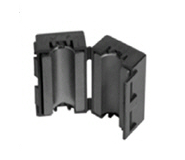
Ferrite bead, cores, and rods, come in a variety of materials called mixes. Some are better at HF frequencies (Mix 31), and some are better at VHF frequencies (Mix 43). While other mixes are available, these are the prime mixes used in amateur mobile chokes.
By the way, surplus beads of unknown mix are a waste of time and resources.
Where to Put Them & Where Not to Put Them
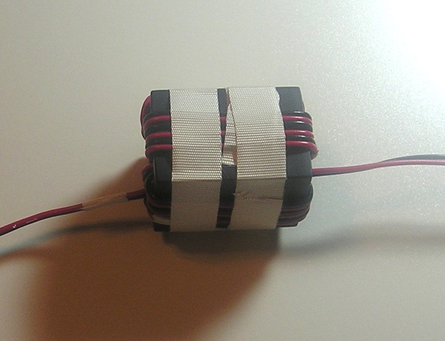
 Probably the most ubiquitous use of ferrite beads is in the form of an antenna motor (and reed switch) lead choke. This requires special winding considerations if the choke is to be maximally effective. In this application, the wires should be parallel wound without twisting to minimize inter-electrode capacitance. The How To Wind A Choke article explains the details.
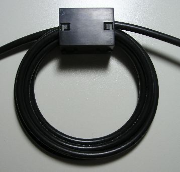
They're also used for common mode current suppression. The loops should be coiled loosely as the left photo indicates to prevent the coax core from migrating. Both motor lead and coax chokes should be mounted as close to the antenna as possible, and outside the vehicle! Remember, any wiring before the choke is part of the antenna, and will radiate.
In some cases, placing them over stereo speaker leads can be an effective way to keep RF out of the final stages of stereo amplifiers. Here too, multiple turns are necessary which might require rewiring existing cabling.
Where not to place them includes low impedance DC power cables. This includes commercial ones advertised to prevent all sorts of maladies—they don't! If you adequately sized your power cabling (see Wiring article), the use of split beads (or brute force filters) is a waste of resources.
Forget about placing them over high-tension ignition wires, as the typical result is increased RFI, not less!
Modern vehicles are awash with computerization. Their digital signals are transported over data networks, as well as discrete circuitry. Examples of the latter are the signals sent to fuel injectors, and COP ignition systems. If you went to the trouble of building harness extensions, to allow installing RF chokes on the feed wires to the injectors and/or COP units, the digital wave form would become integrated (rounded off) which would effect the timing to these systems with obvious consequences.